
 Vitavia Hera assembly guide
Vitavia Hera
Sizes 4500

Pick your size at the top. Quantities and drawings change to match.
The build at a glance
 0 Prepare your base
 1 Build five plain sides
 2 Build the door side
 3 Join the six sides
 4 Build and fit the roof
 5 Build and hang the door
 6 Fit the louvre vent
 7 Fit the glass
Before you start
Six golden rules
- Build side elements loosely. Tighten the bolts joining them only when the frame is square and upright on its base.
- Never overtighten nuts 1002. Maximum torque is 3 Nm. Overtightening strips aluminium and cracks glass.
- Slide every bolt head into its channel before closing the bar. You cannot add bolts afterwards.
- Build with two people.
- Always anchor your greenhouse. An unanchored greenhouse can blow away.
Get ready
- Read the whole guide once before you start.
- Gather flat/PH2 screwdrivers, 10 mm socket spanner/wrench, 10 mm combination spanner, knife, tape measure, spirit level, adjustable-torque cordless drill, step ladder. Set drill torque low.
- Wear gloves, safety glasses, sturdy shoes and a hat. Aluminium edges are sharp. Clear broken glass straight away.
- Open one bundle at a time. Keep opened bundles apart. Mixed bundles are the main cause of lost-part searches.
- Check every part against the parts check pages. Contact Greenhouse Stores before starting if anything is missing.
- Read single-frame drawings as inside views. Read double-frame drawings as outside views.
- Choose a sunny spot with as much wind shelter as possible.
- Hold the step ladder steady whenever the other person is on it.
Parts check
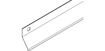
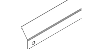
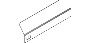
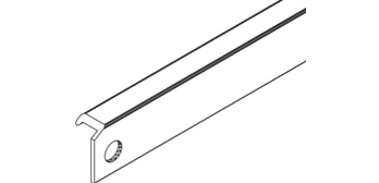
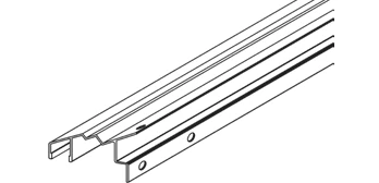
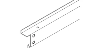
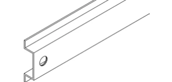
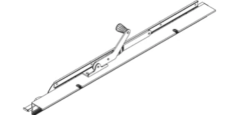
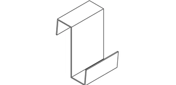
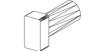
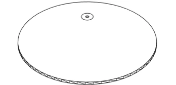
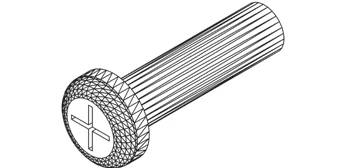
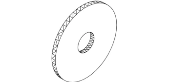
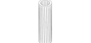
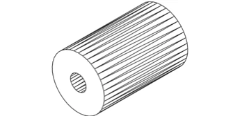
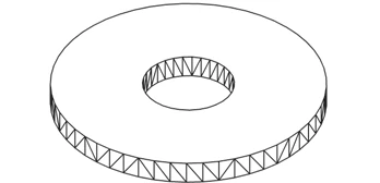
Open one bundle at a time. Tick each part as you find it. The number in green is how many your size should have.
Bars and profiles







Fixings and small parts






Prepare your base
Start with a level base for your six-sided greenhouse.
| 4500 | |
|---|---|
| A across the corners | 2528 mm |
| B across the flat sides | 2189 mm |
Installer tip
Use ground spikes or anchor legs on soil only. On concrete or paving, bolt the base down with suitable fixings. Use one method.
Make your base level; an accessory zinc-coated steel base is available. Follow the regular hexagon drawing: 2528 mm across corners, 2189 mm across flats, 1264 mm sides, 120-degree corners.
For stone or concrete foundations, follow drawing sizes; fix treated timber with 50 mm bolts, not supplied. Use timber at least 18 mm high, no more than 32 mm wide under 6101 or 55 mm under door-side 6102. Foundations must go down below frost level.
On very windy, exposed sites only, drill through the greenhouse bottom profile and steel base. Bolt them together.
Build five plain sides
Build five matching plain side elements flat on the ground, with every bolt loose.
You need
Installer tip
Lay parts on a blanket or lawn to protect the finish. Leave every nut loose so the frame can flex during assembly.
Watch out
Slide bolts into channels through the bar ends. Once both ends are joined, you cannot add bolts.

Join middle bar 6013 to sill bar 6101 at the bottom.
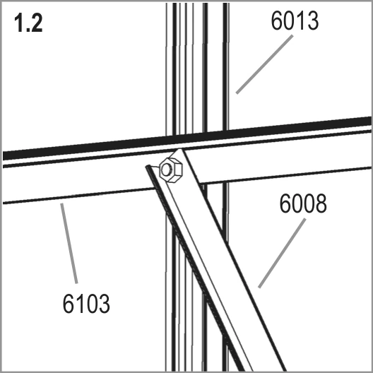
Join bar 6103 and diagonal brace 6008 to middle bar 6013 as shown.

Join middle bar 6013 to eave bar 6110 at the top.

Join the lower end of diagonal brace 6008 to corner bar 6022 at sill bar 6101.
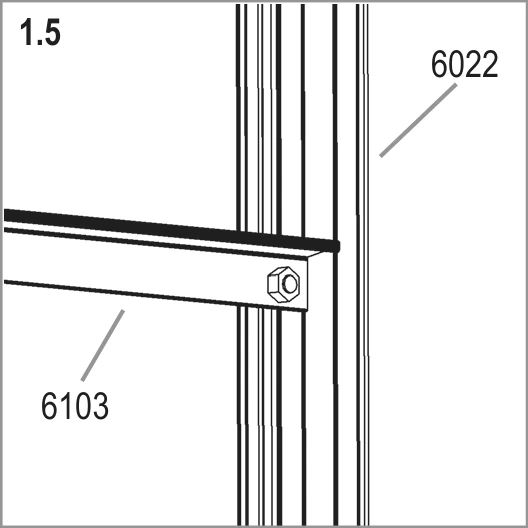
Join bar 6103 to corner bar 6022.
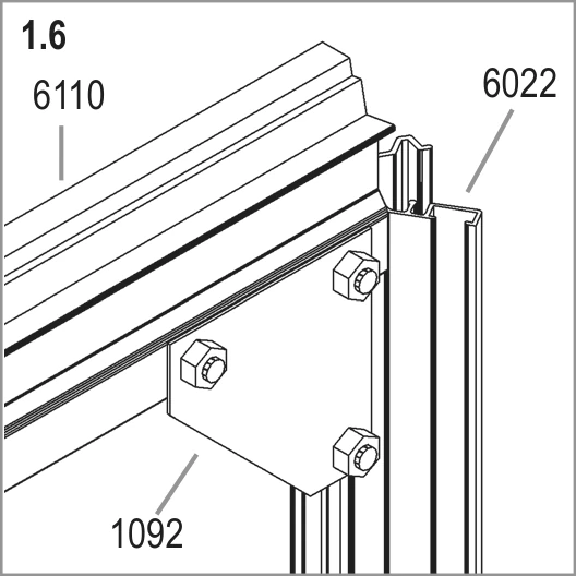
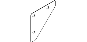
Loosely fit corner plate 1092 where eave bar 6110 meets corner bar 6022.
Slide all bolt heads into each vertical bar's bolt channels as you go. Repeat for the other four plain side elements.
Build the door side
Build the door side element flat on the ground, with every bolt loose.
You need
Installer tip
Check you have sill bar 6102 before starting this side. It has the door track; 6101 does not.
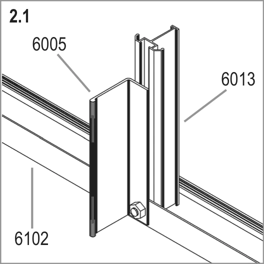
Join bars 6005 and 6013 to sill bar 6102 at the bottom as shown.

Join bar 6104 and brace 6108 to bars 6005 and 6013 as shown.
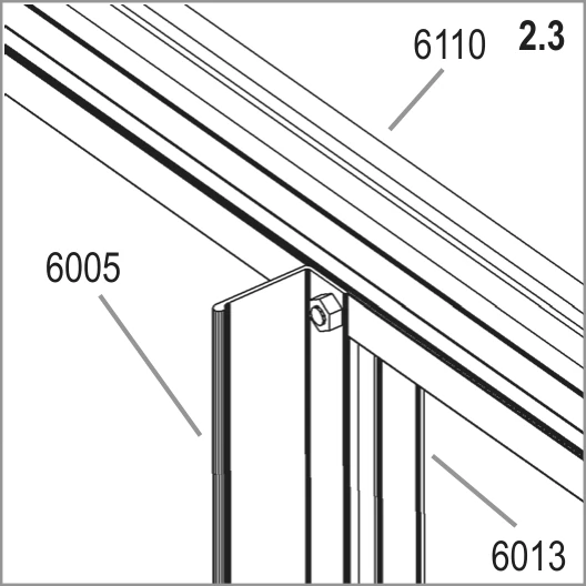
Join bars 6005 and 6013 to eave bar 6110 at the top.
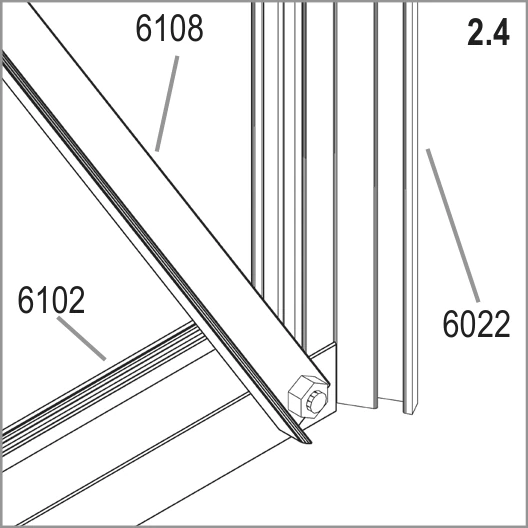
Join brace 6108 to corner bar 6022 at sill bar 6102.

Join bar 6104 to corner bar 6022.

Loosely fit corner plate 1092 where eave bar 6110 meets corner bar 6022.
Join the six sides
Work together to join all six side elements.
You need

Join the side elements at each bottom corner, where corner bars 6022 meet sill bars 6101, as shown.

Join bars 6103 where they meet at each corner bar 6022 as shown.
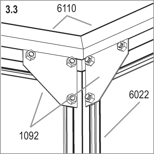
Bolt the side elements together at each top corner with corner plates 1092, below eave bars 6110.
Connect the frame loosely to your prepared base; leave base bolts loose until glazing is complete. Adjust square and upright, then tighten side-joining bolts to a maximum 3 Nm.
Build and fit the roof
Build the roof on the ground in 4A, then lift it onto the walls for 4B.
You need
Watch out
Use a step ladder for the roof. Keep one person holding it steady whenever the other is on it.
Press glazing seal 1020 onto roof bars 6111 and 6112 before assembly, as shown later in 7.2. Cut it to length.
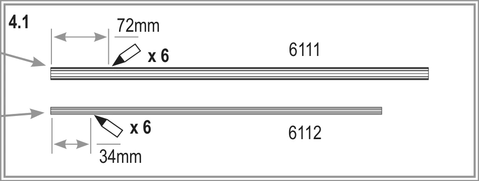
Mark each of the six roof bars 6111 at 72 mm from its end. Mark each of the six bars 6112 at 34 mm, as the cross-section circles show.

Bolt roof bars 6111 and 6112 onto cone 6135 as shown. Tighten all these bolts.

Fit outer cone 6036 over the assembled bars with bolt 6052, washers 6061, spacer 6054 and nut 1002.

With two people, lift the whole roof assembly onto the walls.

Loosely connect roof bars 6111 to eave bars 6110 at all six corners.

Connect roof bars 6112 to the middle of each eave bar 6110. Tighten all bolts.
Build and hang the door
Assemble and square your single sliding door before hanging it.
You need
Installer tip
If the door binds or jumps the track, check the frame is square before forcing it. This is almost certainly the cause.
Lay both vertical bars 6023 down and slide 6 bolts into each bar's channels. Prepare pane 1, 610 x 610 mm, 2 needed; pane 2, 610 x 442 mm, 1 needed.
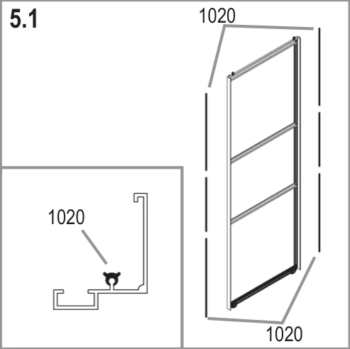
Press glazing seals 1020 onto bars 6023. Cut them to length.

Fit bottom pane 1; loosely join bars 6117 and 6023 using prepared bolts 1001, nuts 1002 and washers 6060. Align 6023 bottoms with 6117's face groove for correct overhang, as shown. Loosely fit wheels 6049 and jump clips 6039 to 6117 with bolt 6046, washers 6051 and nut 1002.

Fit middle pane 2 and loosely connect 6115 to bars 6023 at 5.3a. Fit top pane 1 and loosely connect second 6115 at 5.3b, using washers 6060 and nuts 1002.
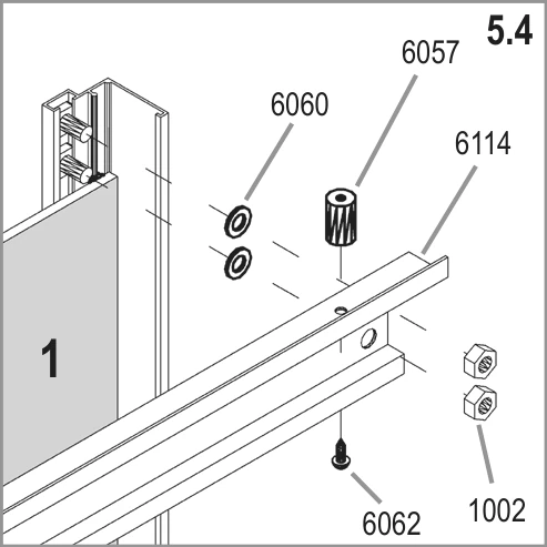
Connect top bar 6114 to bars 6023 with the last four prepared bolts. Screw plastic door guides 6057 onto 6114 with screws 6062.
Measure both door diagonals; they must be equal. Make the door completely square before tightening any bolts.

Put the door in place. Push plastic door guides 6057 upwards into eave bar 6110's channel, as the arrows show.

Lower the door wheels onto sill bar 6102's track. Hook jump clips 6039 under 6102's lip and tighten wheel bolts 6046.
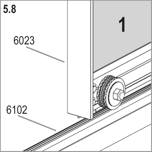
The door wheels run on the track of sill bar 6102.
Fit the louvre vent
Fit your louvre vent into a suitable lower side section; the sidebar lists parts for two louvres.
You need
Choose a section at the bottom of a side without diagonal brace 6008. The louvre fits only here.
Trim the rubber seals in louvre sides 9523 and 9524 to length.
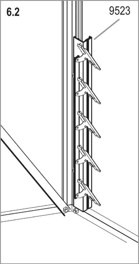
Connect louvre side 9523 with cropped head bolts 2001 in the adjacent upright bar's bolt channel, as shown.

Connect louvre side 9524 similarly with cropped head bolts 2001 and nuts 1002. Fix the two sides to corner bar 6022 and middle bar 6013.
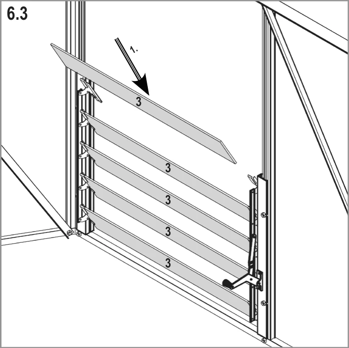
Open the vents and slide in five pane 3 louvre panes, each 549 x 100 mm. Bend the pane guide ends against the panes to hold them firmly.
Fit the glass
Sort your panes, glaze the roof, then work upwards on the sides.
Polycarbonate sheets
This step and its pane table cover horticultural glass. Your polycarbonate sheets are different sizes and use different fixings. We recommend you glaze using the fitting instructions Vitavia packs with your polycarbonate sheets.
Your toughened glass
Your toughened glass comes as full panes, listed in the table below, including your louvre window slats. Use the plan below for pane positions, not the drawing above. Pane 4 is shaped; check your plan for its dimensions.
| Pane | Size (mm) | 4500 |
|---|---|---|
| 1 | 549 x 100 | 10 |
| 2 | 610 x 610 | 2 |
| 3 | 610 x 442 | 1 |
| 4 | 610 x 1208 (shaped, see plan) | 12 |
| 5 | 610 x 1806 | 9 |
| 6 | 610 x 1346 | 2 |
| Total panes | 36 |

You need
Installer tip
Soak glazing seal in hot soapy water first to soften it for fitting. Check pane numbers if glass looks too big; it usually belongs elsewhere.
Watch out
Never force a pane. If it will not seat, square the frame first; forcing glass cracks it.

Sort panes: 1, 610 x 610 mm (31); 4, 610 x 150 mm (2); roof 5, 610/326 x 610/20 mm (12); roof 6, 332/38 x 610 mm (12). Match shapes and positions to drawings.
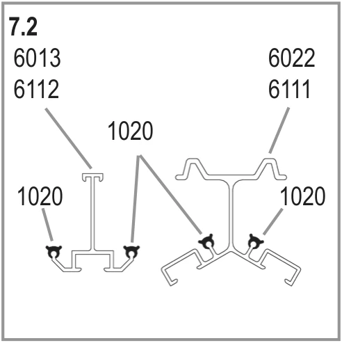
Press glazing seals 1020 onto all aluminium profiles and cut to length. Follow the seal positions shown on bars 6013 and 6112, and bars 6022 and 6111.
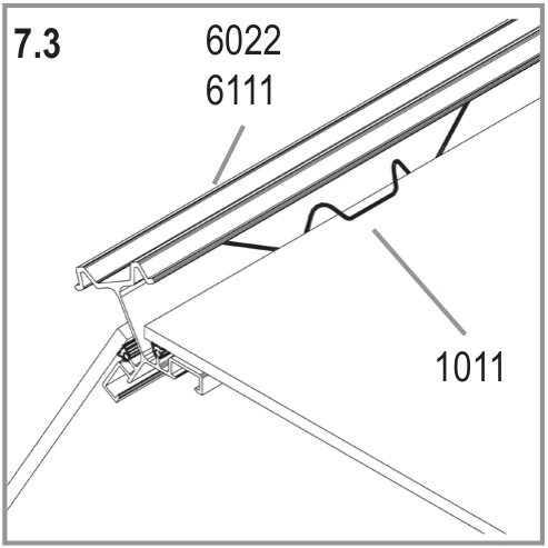
Use the step ladder inside to glaze the roof through open roof spaces. Secure panes with spring clips 1011 along roof bars 6111, and corner bars 6022 on the sides.
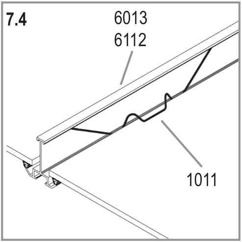
Fit glazing spring clips 1011 similarly along roof bars 6112, and middle bars 6013 on the sides.

Tuck each roof pane 5's top edge beneath pane 6's bottom edge, with retaining clip 1012 between them. Seat pane 5's lower edge in the eaves recess.
Glaze the sides from the bottom upwards.
Tighten the bolts holding the greenhouse to the base.
Horticultural glass for your greenhouse
| Pane | Size (mm) | 4500 |
|---|---|---|
| 1 | 610 x 610 | 31 |
| 4 | 610 x 150 | 2 |
| 5 | 610/326 x 610/20 | 12 |
| 6 | 332/38 x 610 | 12 |
| Total | 43 |
Pane numbers match the glazing layout in the drawing above.
Finish and look after it
Finish
- Anchor your greenhouse. This is not optional.
- Seal the edges with neutral silicone if you wish. Silicone is not supplied.
- Stick the warning label inside the greenhouse.
- Stick the model label onto door top bar 6114. Keep it there for spare parts orders.
- Keep this guide somewhere safe.
Looking after it
- Shut the door and all vents in high winds.
- Clear or support the roof in heavy snow. Heat the greenhouse in winter.
- Wash occasionally with a mild detergent that does not attack aluminium or plastic.
- Keep the door track clean to prevent dirt build-up.
- Add the greenhouse to your home insurance. Check local building rules about its position.
Drawings reproduced from the Vitavia assembly instructions (Vitavia manual 014.02.1109 (Hera 4500)). Greenhouse Stores, greenhousestores.co.uk.