
 Vitavia Ida assembly guide
Vitavia Ida
Sizes 900, 1300

Pick your size at the top. Quantities and drawings change to match.
The build at a glance
 0 Prepare the base
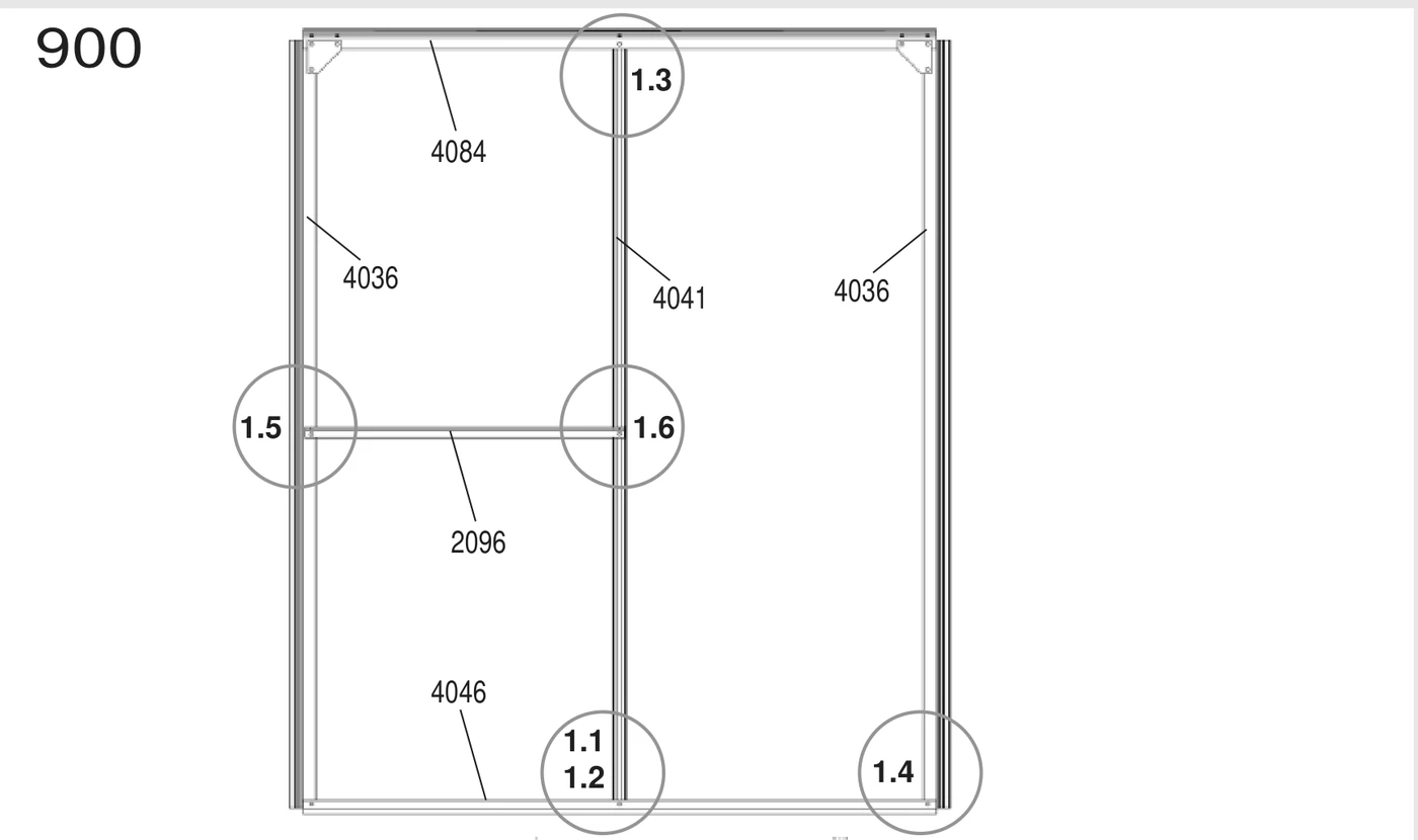 1 Build the front wall
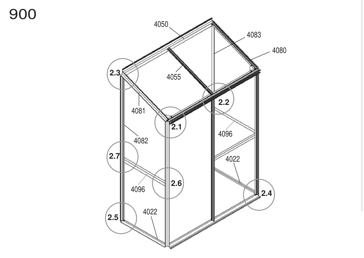 2 Build ends and roof
 3 Fix to the house wall
 4 Build and hang the door
 5 Build and fit the vent
 6 Fit the panes
Before you start
Six golden rules
- Build frames loose. Tighten only when the whole greenhouse is square on its base, with both diagonals equal.
- Do not overtighten nuts and bolts.
- Fit extra bolts when instructed. Each roof glazing bar needs one for the roof vent.
- Before fixing to the house wall, make sure the sides are perfectly vertical.
- Build with two people.
- Do not force any part or pane that will not fit.
Get ready
- Read the whole guide once before you start.
- Gather flat/PH2 screwdrivers, 10 mm socket spanner/wrench, 10 mm combination spanner, knife, tape measure, spirit level. Set cordless drill adjustable torque low.
- Wear gloves, safety glasses, sturdy shoes and a hat. Aluminium edges are sharp. Clear up broken glass straight away.
- Open one bundle at a time and keep opened bundles apart. Mixed bundles are the main cause of lost-part searches.
- Check every part against the parts check pages. Contact Greenhouse Stores before you begin if anything is missing.
- Read single-frame drawings as views from inside the greenhouse. Read double-frame drawings as views from outside.
- Choose a sunny spot with as much shelter from wind as possible.
Parts check
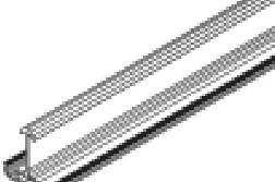
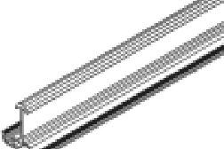
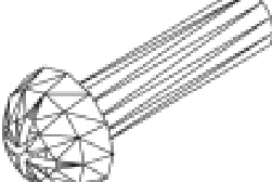
Open one bundle at a time. Tick each part as you find it. The number in green is how many your size should have.
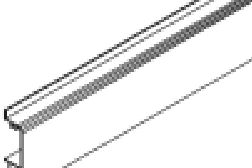
Bars and profiles




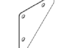






Fixings and small parts









Prepare the base
Start with an exactly square, level base at 90 degrees to the house wall.
| 900 | 1300 | |
|---|---|---|
| A | 653 mm | 653 mm |
| B | 1300 mm | 1922 mm |
Installer tip
Use ground spikes or anchor legs only in soil. On concrete or paving, bolt down with suitable fixings; use one method, not both.
Watch out
If the base is not square and level, the frame above will not be either. Panes will not fit an out-of-square frame.
Measure both diagonals and check they match, as shown by X = X. Use an exactly square, level base; a zinc-coated steel base is sold separately.
Only if you build your own stone or concrete foundation, use this page's A and B sizes below frost level. Between foundation and aluminium frame, fit treated timber at least 18 mm high and no more than 32 mm wide, fixed to the foundation with 50 mm bolts not supplied.
On a very windy, exposed site, drill through both the greenhouse bottom profile and the steel base. Bolt them together.
Build the front wall
Build the front wall flat on the ground, and leave every bolt loose.
You need

Installer tip
Lay the parts on a blanket or the lawn to protect the finish. Leave every nut loose so the frame can flex when you fix it square in step 3.
Watch out
Follow the drawing for your size. The 1300 has two bars 4041 and two bars 2096; the 900 has one of each.
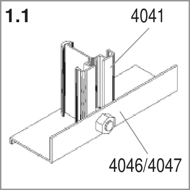
Bolt the bottom of bar 4041 to your bottom bar (4046 or 4047).
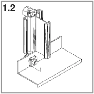
Slide a bolt into the channel of your bottom bar (4046 or 4047), as the arrow shows. Join bar 4041 to it as shown.

Bolt the top of bar 4041 to your eaves door track (4084 or 4085). Loosely connect corner plates 1092 at the two upper corners.
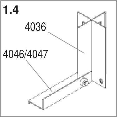
At each end, bolt bar 4036 to your bottom bar (4046 or 4047).
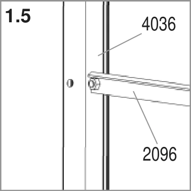
Bolt bar 2096 to bar 4036.
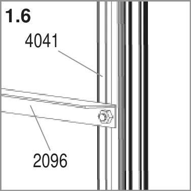
Bolt the other end of bar 2096 to bar 4041.
Build ends and roof
Follow the drawing for your size, and keep all bolts loose.
You need

Installer tip
Slide the extra bolt into each roof glazing bar 4055 before you fit the bar.
Watch out
Do not miss the extra bolt in each roof glazing bar 4055. You need it to fix the roof vent in step 5.
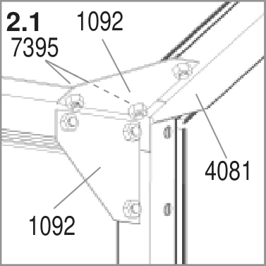
Connect gable end bars (4080 and 4081) to your eaves door track (4084 or 4085), with washers 7395 at every connection. Loosely fit corner plate 1092 above the eaves.
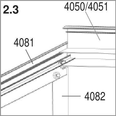
Connect gable end bars (4080 and 4081) to vertical wall bars (4082 and 4083). Connect them to your ridge bar (4050 or 4051) as shown.
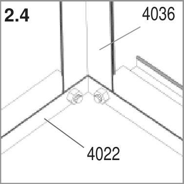
Bolt sill bar 4022 to bar 4036 at the front corner.

Bolt sill bar 4022 to vertical wall bar 4082 at the wall end.
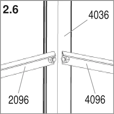
Bolt bar 4096 and bar 2096 to bar 4036 as shown.
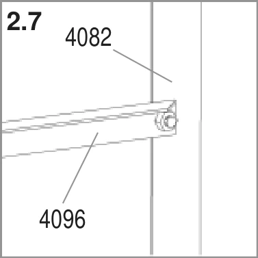
Bolt the other end of bar 4096 to vertical wall bar 4082.

Connect roof glazing bars 4055 between your eaves door track and ridge bar, with washer 7395 at the eaves. Fit one on the 900, two on the 1300; insert one extra bolt into each.
Fix to the house wall
Work with two people to square the frame and fix its back to the house wall.
You need
Installer tip
Check that the sides are perfectly vertical before you mark the holes on the wall.
Watch out
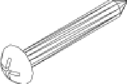
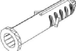
Screws 2002 and wall plugs 2003 are supplied. The drill is not included.
Place the greenhouse on the prepared base or foundation and connect loosely; adjust until square, with both diagonals equal. Tighten all bolts without overtightening, and make sure the sides are perfectly vertical.
Mark pre-drilled holes in vertical wall bars (4082 and 4083) and your ridge bar (4050 or 4051) on the wall. Lift off the frame; drill 6 mm holes and insert supplied wall plugs 2003.
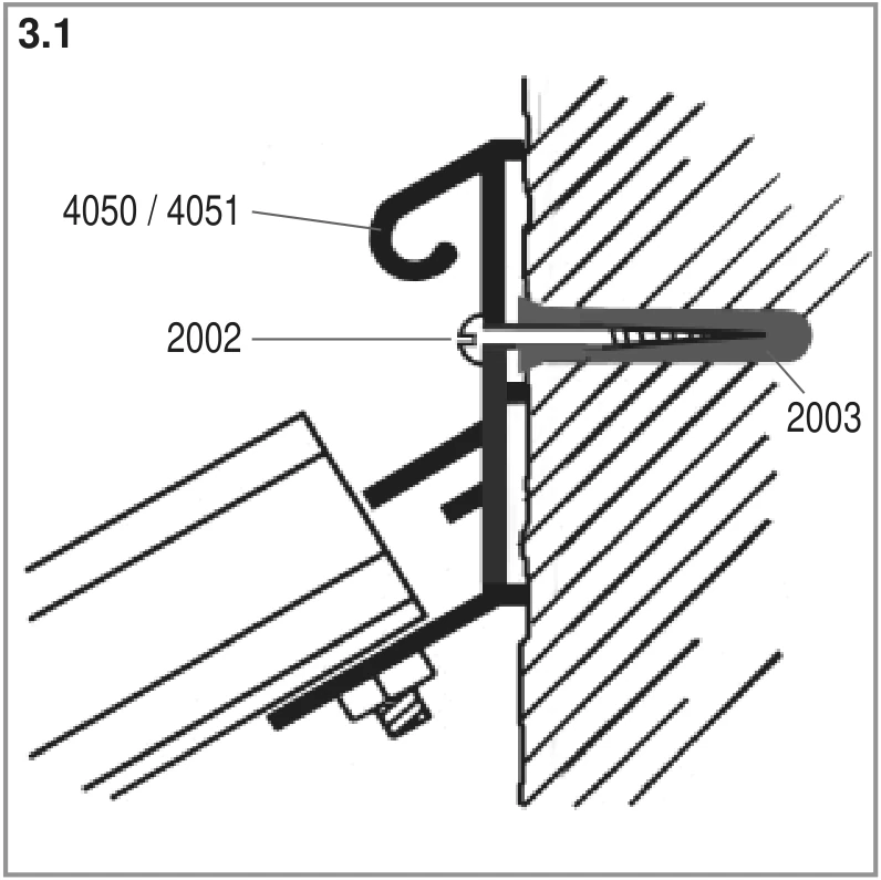
Put the frame back on the base. Screw your ridge bar (4050 or 4051) to the wall with screws 2002 and wall plugs 2003.

Screw vertical wall bars (4082 and 4083) to the wall with screws 2002 and wall plugs 2003, as shown.
Finally, fix the frame to the base if you wish.
Build and hang the door
Assemble the sliding door, then lift it into the tracks.
You need
Installer tip
If the door binds or jumps the track, the frame is almost certainly not quite square. Go back and check before you force it.
Watch out
Never stand the assembled door on its gliders 1014. This damages them.
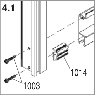
Push a door glider 1014 onto each end of door bar 1060. Screw side bar 4058 to it with screws 1003.
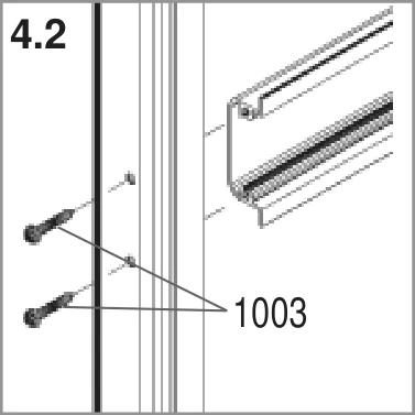
Screw the two bars 1061 to side bars 4058 with screws 1003.
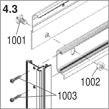
Bolt door bar 1062 to upper bar 1059 with bolt 1001 and nut 1002. Screw the side bar to it with screws 1003.
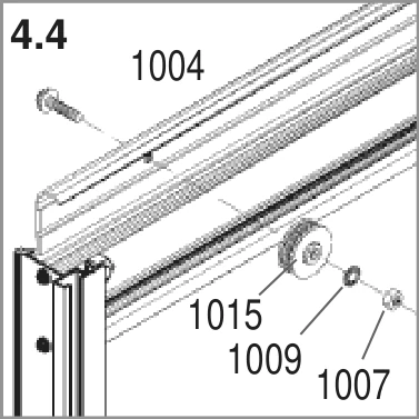
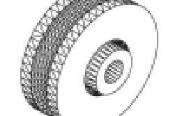
Fix the two door rollers 1015 to door bar 1062 with bolt 1004, washer 1009 and nut 1007.
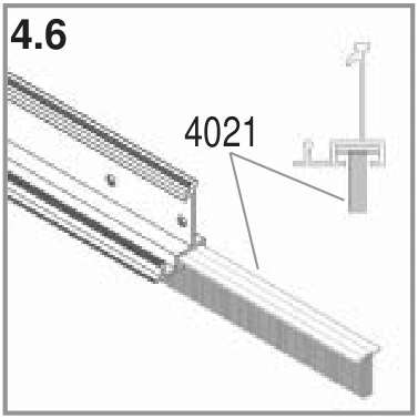
Slide a door seal 4021 into each side bar 4058.
Connect door fixer parts 1111, 1112 and 1113 to door bar 1062, as the door drawing shows.
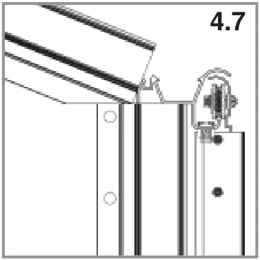
Lift the door and slide door rollers 1015 into your eaves door track (4084 or 4085).
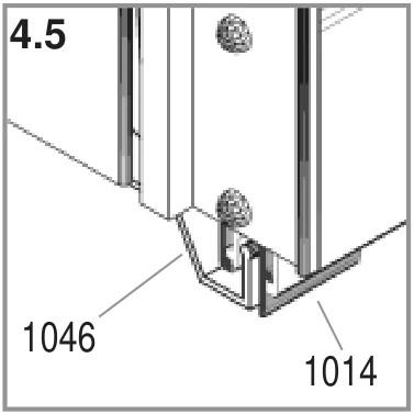
Check that door gliders 1014 also run in the bottom track.
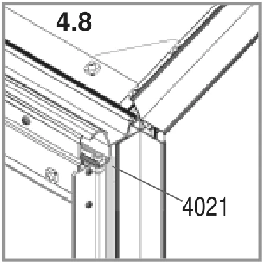
Check door seal 4021 is in the side bar at the hung door's top corner, as shown.
Put a nut and bolt into both ends of your eaves door track (4084 or 4085) as door stops. Adjust the door until it slides freely.
Build and fit the vent
Assemble the roof vent, check it is square, then hook it into the ridge bar.
You need
Installer tip
Fit the slam bar (window sill 1063) flat edge up, with its grooved lip down towards the pane below. If that pane will not sit snugly, recheck the slam bar.
Watch out
On the Ida 1300, fit the vent in the middle section if you can. Use the extra bolts already in roof glazing bars 4055; bolt 2001 is not needed.
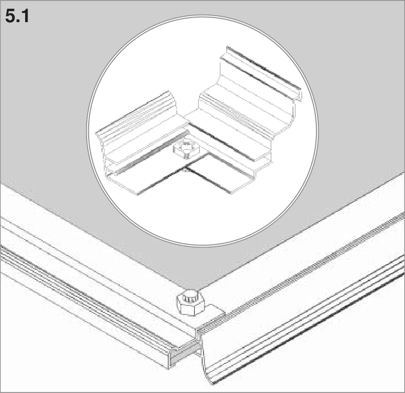
For glass up to 4 mm thick, join side bars 1065 and top bar 1064 as shown.
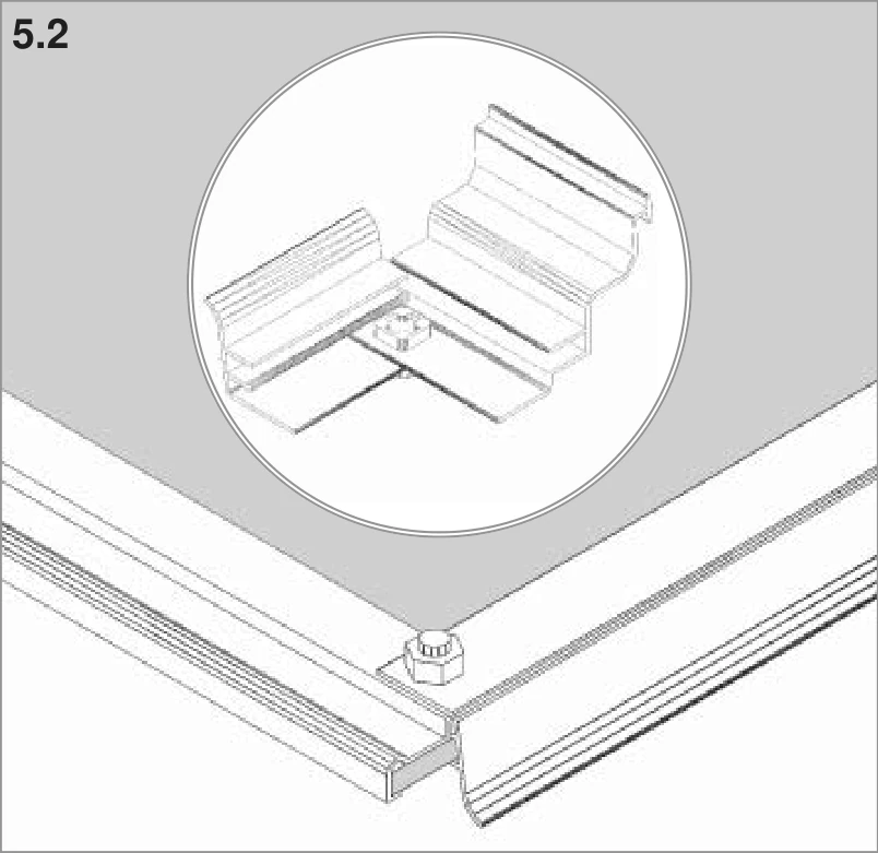
For glass 4 mm or thicker, join side bars 1065 and top bar 1064 as shown here instead.
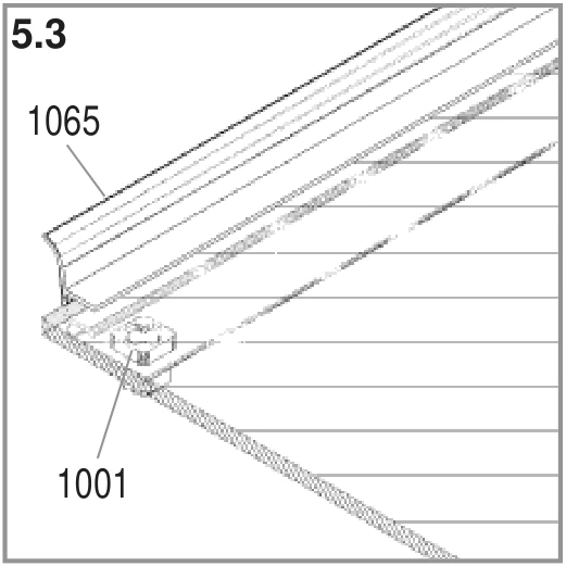
Put bolts 1001 for bottom bar 1066 into the prepared holes; slide the vent glass into side bars 1065. Fit bottom bar 1066 and check the vent is completely square before you tighten the bolts.
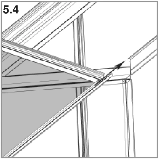
Hook the vent into the ridge bar from one end of the greenhouse.
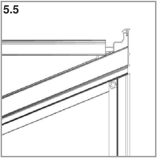
Hook vent top bar 1064 over your ridge bar (4050 or 4051), as shown.
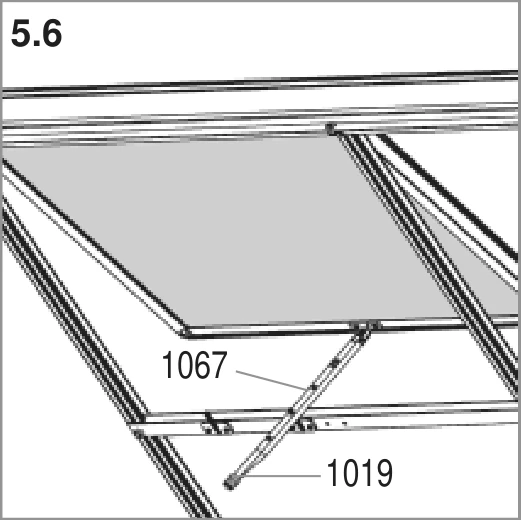
Slide the vent along to your chosen position. Push plastic cap 1019 over the end of window opener 1067.

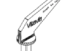
Fix window sill 1063 to each roof glazing bar's extra bolt and the corner bar with bolt 2001, as shown. Screw both window fixers 1016 onto window sill 1063 with screws 1006.
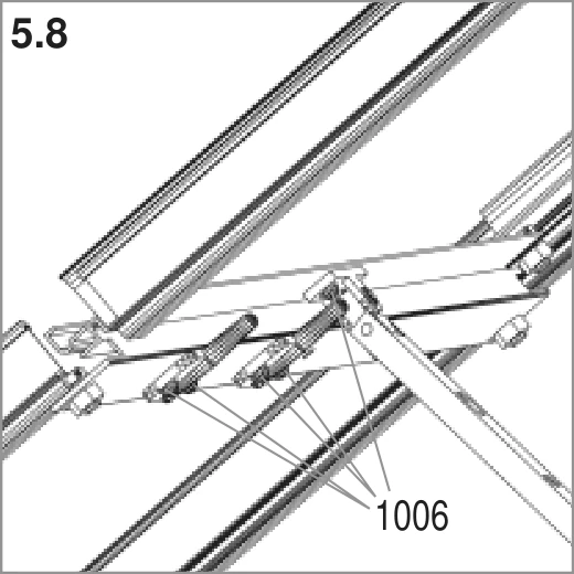
Screw window opener 1067 to vent bottom bar 1066 with screws 1006.
Fit the panes
Fit the glazing seal before any panes, then follow the roof and side glazing order.
You need
Installer tip
We recommend you soak the whole seal reel in hot soapy water first; it softens and presses on more easily. If a pane looks too big, check the glazing layout for a different opening.
Watch out
Never force a pane. If it will not seat, correct the out-of-square frame first.
Choose any front section for the door. Leave that section free for now.
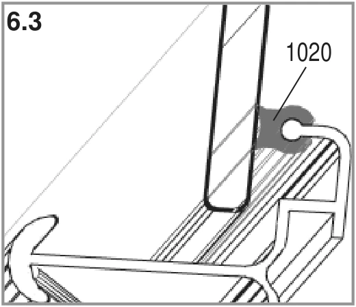
Press glazing seal 1020 onto the aluminium profiles and cut it to length. Do this before you fit any pane.
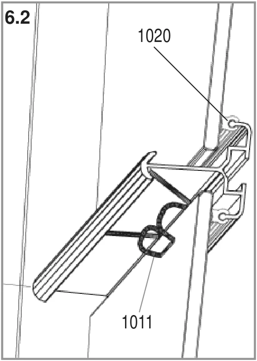
Start the roof glazing at the ridge. Fix the first pane with glazing spring clips 1011.
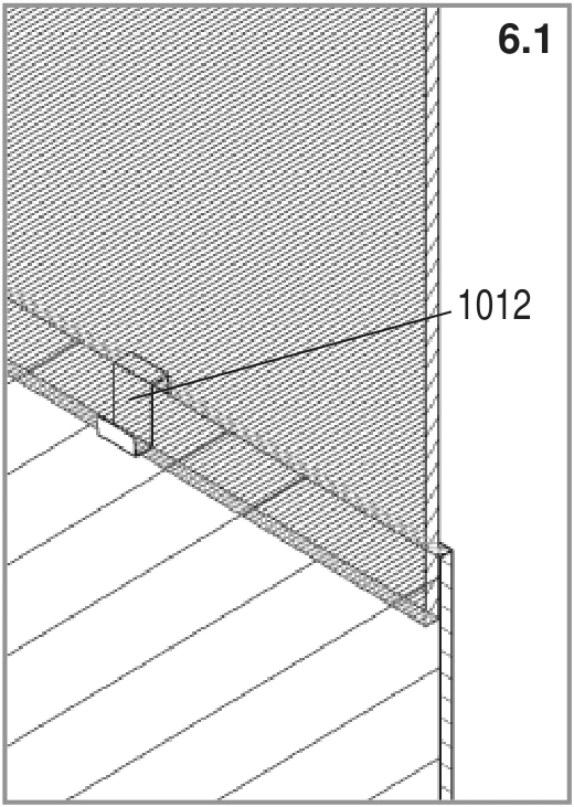
Slide each next pane under the pane directly above it. Put retaining clips 1012 between the panes.
Glaze the sides upwards from the bottom; if the last pane is difficult, check panes above have not slipped down. For polycarbonate sheets, also follow the instructions packed in their carton.
Glass for your greenhouse
| Pane | Size (mm) | 900 | 1300 |
|---|---|---|---|
| 1 | 610 x 508 | 11 | 14 |
| 2 | 610 x 343 | 2 | 4 |
| 3 | 610 x 307 | 1 | 1 |
| 4 | 610 x 267 x 21 | 2 | 2 |
| 5 | 610 x 127 | 1 | 1 |
| 6 | 600 x 544 | 1 | 1 |
| Total | 18 | 23 |
Pane numbers match the glazing layout in the drawing above.
Finish and look after it
Finish
- Seal the edges with neutral silicone if you wish; it is not supplied.
- Stick the warning label inside the greenhouse.
- Stick the model label onto door bar 1062. You will need it to order spare parts.
- Keep this guide somewhere safe.
Looking after it
- Shut the door and roof vent in high winds.
- Clear the roof or support it in heavy snow. Heat the greenhouse in winter.
- Wash occasionally with a mild detergent that does not attack aluminium or the glazing clips.
- Keep the upper and lower door tracks clean so grit does not build up.
- Add the greenhouse to your home insurance, and check local building rules about where it can go.
Drawings reproduced from the Vitavia assembly instructions (Vitavia manual 003.01.1101 (Ida 900 and 1300, polycarbonate)). Greenhouse Stores, greenhousestores.co.uk.